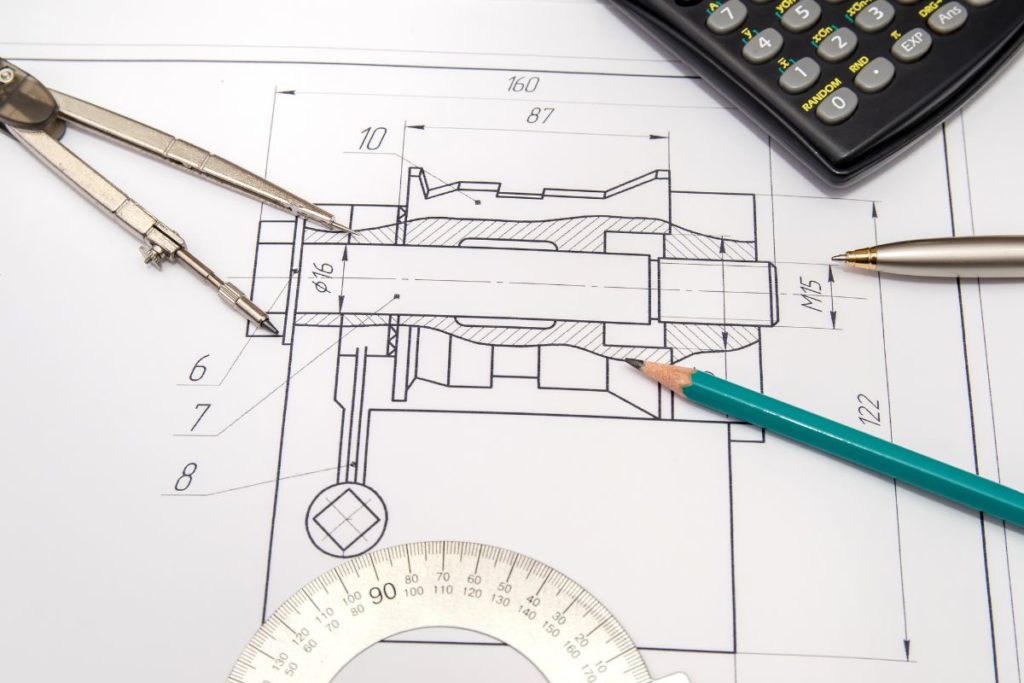
Engineers, designers, and architects rely heavily on engineering drawings to convey their ideas and plans to others in the construction industry. It is a graphical representation of an object, machine, or structure that includes all relevant characteristics and dimensions. Therefore, views are crucial in engineering drawings to communicate an object’s form and dimensions effectively. In this article, a discussion of the various types of views in engineering drawings will take place.
- Orthographic Perspective
When creating an engineering drawing, orthographic perspectives are typically used. These are two-dimensional views of an object in which each side of the object is depicted as a different image. Orthographic views usually display the top, front, and right angles. This perspective helps convey details about the object’s size and shape.
- Isometric Perspective
As a three-dimensional (3D) view, an isometric perspective displays a subject’s shape, size, and location in a single image. It’s a helpful way to portray complex objects so that viewers can understand what they look like from all sides. Lines that depict the thing in an isometric view are also drawn at a 120-degree angle, making the three axes coincide.
- Oblique View
The difference between an oblique view and an isometric perspective is that the former shows only one side of the object. The standard practice is displaying the object’s face at a 45-degree angle while displaying the other faces in their dimensions. This perspective helps visualize an object from various angles, demonstrating its depth and height.
- Sectional View
A form known as a sectional view illustrates the composition of an object’s interior components. It occurs by severing a section of the thing to expose its internal structure. This perspective is helpful for illuminating details on the interior of an object that would otherwise be hidden from view.
- Auxiliary View
An auxiliary view is intended to reveal the actual dimensions of a steep or oblique surface. It’s a projection of a three-dimensional scene onto a plane that runs perpendicular to the surface of interest. Since a surface’s actual dimensions and contour cannot be conveyed via orthographic views, this perspective is invaluable.
- Exploded View
An exploded view’s purpose is to demonstrate a given object’s structure by breaking it down into its component parts. Each component of the thing is displayed in its proper location concerning the others as if the entity had exploded. It is helpful to demonstrate how an object is put together using this particular style of view.
- Perspective View
A perspective view simulates how an object looks to the human eye from a specific distance. This perspective from three dimensions renders the object with accurate depth, shadows, and foreshortening. This perspective helps demonstrate how an object seems in the actual world.
Conclusion
Combining many viewpoints in an engineering drawing is crucial for effectively conveying the object’s design. Orthographic views, isometric views, oblique views, sectional views, auxiliary views, exploded views, and perspective views are all common in engineering drawings. In addition, a variety of perspectives are available, each of which has a unique set of benefits and may be utilized to represent a variety of elements of an item effectively.

